The Christmas holidays are coming and the darkest part of the winter is here, only 4 hours of light each day. I have time, again, to work on my 6S45P amplifier continued from part two.
I´ve finished it in this part so here are all the links to this story:
The simplest amplifier obsession Part 0
Breadboard amplifier Part 1
Chassis building Part two
Assembling the 6S45P amplifier Part three – this one.
Finalizing the 6S45P Part four
Her goes the story:
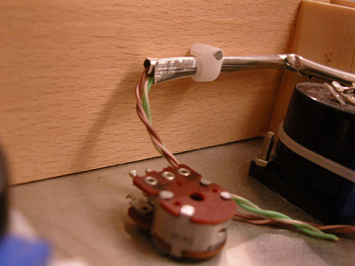
Today I began soldering the output transformer to the banana sockets in the back of the amp. The wire was bent and zip-tied in place to give a neat appearance. I am hoping to finish this amp really neatly inside since it is so simple. I also mounted the signal input wires from the RCA plugs. I used CAT 5 twisted pairs encapsulated in thick aluminum foil to avoid hum. The wire package was tacked to the inside frame to be as far from the power supply as possible.


Now I had to decide on an operating point. The datasheet recommends 30mA at 150V, but several builders have tested the tube to be robust far beyond that point. After experimenting on the breadboard earlier this year I decided on operating the 6S45P at 175V and 40mA which will put the operating point just below the recommended power dissipation limit shown as the purple curve. In the diagram below the red lines point at the operating point, and the green line shows the voltage swing with an input of 2 Volts, typical max from a modern CD player. The slope of the green line is calculated by finding how much current is lost over 100Volts when loaded with the 5000ohm transformer. I=U/R so 100/50000=0.02A. So the slope is 20mA per 100Volts.

Next I built the power supply, which is the most components in the design. This amp is almost only a power supply and 5 other components. I simulated the power supply, roughly, in Duncan Amps PSUD2. Since I was using the Russian 5Ц4С I found nearest equivalent 5Z4P (unfortunately not G) data on Duncan amps pages and added to PSUD2´s rectifier list. The transformer is 240 to 190-0-190v and I used rectifier load of 5K to simulate my 5K output transformer. Usually it is recommended to use current draw for the operating point, but it did not seem to match my breadboard results. A confounding factor was not having the precise manufacturers data on the transformer or 5U4S in PSUD2.
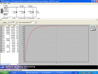 |
| Closest approximation in PSUD2 with Resistive load 5k. |
I built the power supply´s smoothing section on a piece of experimenters board bolted at 90 degrees to the chassis. I could have isolated the board creating a better star ground point, but was impatient to get going. The power transformer has several optional taps that I cut short, isolated with heat shrink, and zip tied. At this point the dream of clean wiring started to crumble – as it usually does!
 |
| First capacitor 3uF to the left, then 100uF, 100R, 100uF, 100R, red wire i B+. |
|
 |
Angle brackets keep the board in place. Green/Yellow wire is heater for the rectifier.
Important: the bleeder resistor is connected between the two 100uF caps to drain them at power of. |
 |
| Overview of the power supply. The switch is not mounted to the brown wire yet. I prefer switching through a ground fault protection switch. |
Next I wired up the amplifier tubes. The 6S45P has several connecting points for cathode and grid. you only need to use one, so I chose the ones that reduced crossed wires to a minimum.
for novices pins are counted clockwise as seen from under the socket. starting from the gap on nine pin mini or from the key on octal sockets.
 |
| Socket wiring: Yellow pin 4 and 5 is heater, Orange pin 6 is cathode, Blue pin 7 is plate, Green pin 8 is grid and black in the middle is a local start ground for this channel. |
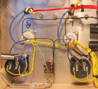 |
| The mA meter is connected to ground and then the cathode bias is created by series connecting a 22ohm resistor to a 50ohm trim potentiometer. A 470uF 35V capacitor is connected in parallel to the resistors. the light in the mA meter is fed 6.3v ac in parallel to the heaters. |
 |
| Here is the first attempt at wiring. Not so neat after all. As usual. The yellow ac heater wires should not be routed out into the circuit, but kept along the side. |
First power up. Oh why do I never get round to finishing that variac and light bulb load? I connect three multimeters to B+, filament 6.3v and 5 volt, the onboard mA meters show me the current. Connect the amp through a ground fault switch, and hope for the best …. NO Smoke! The rectifier takes about 10 seconds to conduct properly. All voltages pretty good. I need to reduce minimum cathode resistance to get to 40mA. I can´t adjust it with the 33ohm limiting resistor I have now. Test with sound. One channel has a bad contact. After powering down and waiting for capacitors to drain I locate it by poking at contacts with a screwdriver. Its a resistor in the cathode circuit. Now all I have to do is mount the switch and build the bottom.
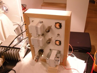 |
| I use some pieces of wood to support the transformer |
 |
| Three voltmeters and the dummy load connected for first power up. Also I have a automatic ground fault switch connected to the mains cord, and switch mains of remotely. |
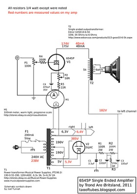 |
The final schematic with measured voltages in red. A perfect beginners project!
UPDATE: I am not completely happy with Musical Power supplies for this application due to to the magnetic field inducing hum in trafo cover. I did have some hum, and when reworking the layout hum in the transformer also was reduced. you might consider equivalent Edcor or even Sowther power transformers. |
There a often discussions about what is the best beginners tube amplifier on forums like DIY Audio etc. I think this amplifier is the best place you can start because voltages are relatively low. (still deadly tho). You can follow up the amplifier build with a nice 95dB/w full range speaker and spend some quality time wondering why people spend tens of thousands on high end equipment.
If you want to build this amplifier really simply, take a look at how I did it on the breadboard version. Drop the ampere meter and the trimmer pot on the cathode. Drop the tube rectifier and go for a cheaper lower power output transformer. With a cheap 220v to 120v transformer in a 240v country you will get close to 175v B+ using a normal bridge rectifier, 1 amp 600v should do, and capacitor resistor capacitor (CRC) smoothing, but make sure the transformer is a little over size to handle the extra voltage. Maybe 500mA or so. For heater use a 3 Amp 240 to 12 volt transformer and wire the tubes in series. And never leave out the grid stopper resistor soldered right up to the grid tag on the socket. The 6S45P can become a high frequency ADHD squirel if you do 🙂
Here are all the links to this story:
The simplest amplifier obsession Part 0
Breadboard amplifier Part 1
Chassis building Part two
Finishing the 6S45P amplifier Part three – top of this one.


